Tampilkan postingan dengan label Networking. Tampilkan semua postingan
Mikrotik sebagai gateway adalah salah satu konfigurasi yang paling
sering ditemui selain sebagai manajemen bandwidth. Mikrotik sebagai
gateway maksudnya adalah router mikrotik dimanfaatkan sebagai pintu
gerbang tempat keluar masuknya paket dari dan ke internet, jadi semua
paket akan dilewatkan melalui Mikrotik. Topologi yang digunakan pada
jaringan model ini sangat sederhana, karena konfigurasi ini juga adalah
konfigurasi dasar bagi seseorang yang ingin belajar tentang Mikrotik.
Setiap orang yang ingin belajar tentang Mikrotik harus bisa melakukan
konfigurasi ini. Berikut gambar yang saya buat untuk menggambarkan
topologinya.

Settingan yang digunakan juga sangat sederhana. Berikut ini akan saya perlihatkan settingan Mikrotik sebagai gateway menggunakan Winbox. Disini saya menggunakan PC Router yang saya instal Mikrotik versi 3.20 dan saya pasangkan 2 buah kartu jaringan, dimana pada port pertama saya colokkan kabel yang berasal dari ISP, dan port kedua saya colokkan ke Switch yang terhubung ke LAN. Anda juga bisa menggunakan Router Board, sama saja.
1. Persiapan Awal
Selanjutnya adalah memberikan komentar pada masing-masing interface agar mudah kita kenali, mana yang untuk ke ISP dan mana yang untuk ke LAN:
Untuk memberikan IP Address lakukan langkah berikut ini:
Agar jaringan lokal bisa melakukan akses ke jaringan luar (internet), maka harus dibuat routing table. Agar paket memiliki arah tujuan yang jelas dan paket tersebut tahu bagaimana cara dia menuju tujuannya, caranya adalah:
Tujuan membuat NAT rule adalah agar paket bisa dilewatkan ke jaringan luar atau internet. Agar paket yang berasal dari interface lokal [ethe2] bisa sampai ke tujuannya dengan melewati interface internet [ether1]. Caranya adalah sebagai berikut:
DNS digunakan sebagai penerjemah dari nama domain ke alamat IP, dan sebaliknya, yaitu dari alamat IP ke nama domain. Jadi apabila pengguna mengetikkan google.com di web browser, maka itu berarti pengguna memanggil alamat IP dari google.com yaitu 74.125.71.103. caranya adalah sebagai berikut:
Setelah itu langkah terakhir dari seting di router adalah melakukan pengecekan apakah konfigurasi yang dilakukan sudah benar atau belum. Caranya adalah:
Selanjutnya adalah melakukan tes koneksi ke internet dari klien, namun sebelumnya IP Address dari klien harus diatur sesuai dengan konfigurasi yang telah dibuat. Berikut adalah konfigurasi klien sesuai dengan konfigurasi yang penulis buat dari Windows XP:
IP Address : 192.168.1.1
Subnet mask : 255.255.255.0
Default Gateway : 192.168.1.254
Preferred DNS : 203.130.196.155
Alternate : 8.8.8.8
Lakukan ping dari Command Prompt ke salah satu domain di internet, misalnya google.com dengan mengetikkan perintah [ping google.com]. jika ada reply itu berarti konfigurasi sudah berhasil. Jika belum coba lebih teliti lagi dalam melakukan konfiurasi. Selamat mencoba.
sumber : http://kurniawanadam.wordpress.com
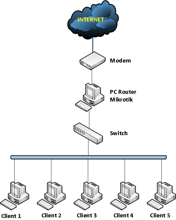
Settingan yang digunakan juga sangat sederhana. Berikut ini akan saya perlihatkan settingan Mikrotik sebagai gateway menggunakan Winbox. Disini saya menggunakan PC Router yang saya instal Mikrotik versi 3.20 dan saya pasangkan 2 buah kartu jaringan, dimana pada port pertama saya colokkan kabel yang berasal dari ISP, dan port kedua saya colokkan ke Switch yang terhubung ke LAN. Anda juga bisa menggunakan Router Board, sama saja.
1. Persiapan Awal
- Hidupkan PC Router
- Pastikan semua sudah terpasang dengan baik seperti topologi diatas.
- Nyalakan salah satu komputer client untuk mensetting PC Router Mikrotik menggunakan Winbox. Kalau belum punya software Winbox, silahkan download di situs Mikrotiknya.
- Jalankan Winboxnya.
- Maka akan muncul jendela kecil, yaitu tampilan awal dari Winbox.
- Klik tombol yang memiliki tiga titik […] disamping tombol [Connect]
- Jika Routernya sudah terkoneksi dengan baik ke LAN, maka akan muncul sebuah list yang berisikan MAC Address dan IP Address.
- Klik saja MAC Addressnya, lalu klik [Connect]
- Maka akan muncul jendela admin dari router Mikrotik yang diremote menggunakan Winbox.
- Apabila PC Router Mikrotik yang Anda gunakan ini sebelumnya sudah pernah disetting, maka lakukanlah reset ulang agar semua settingan kembali seperti awal pada saat belum dilakukan setting apapun. Caranya adalah klik tombol [New Terminal].
- Maka akan muncul sebuah jendea yang memiliki latar belakang putih.
- Ketikkanlah pada jendela putih itu tulisan, [system reset], jika diminta memilih Yes atai No, pilih saja Yes dengan menekan tombol [Y].
- Setelah di reset biasanya router akan terdisconnect, konekkan kembali dengan langkah yang sudah dijelaskan sebelumnya.
- Maka akan muncul jendela yang menanyakan, apakah akan menggunakan settingan default dari Mikrotik atau ingin menggunakan settingan sendiri. Klik [Remove Configuration] karena kita akan melakukan settingan sendiri.
- Lalu agar mudah untuk diidentifikasi berikanlah nama untuk router yang digunakan. Dari [System] > [Identify]. Ketikkan nama router yang Anda inginkan, klik [Ok]. Disini saya memberikan nama [Gateway]. Sampai disini router sudah siap untuk dikonfigurasi.
Selanjutnya adalah memberikan komentar pada masing-masing interface agar mudah kita kenali, mana yang untuk ke ISP dan mana yang untuk ke LAN:
- Klik [Interface].
- Klik pada interface [ether1].
- Klik icon yang bergambar kertas berwarna kuning, lalu isika komennya. Disini saya memberikan komen [TO INTERNET], karena interface ini yang akan menuju internet.
- Begitu juga untuk [ether2]. Saya berikan komen [LOKAL]. Karena
interface ini yang akan terhubung langsung ke jaringan lokal [LAN].

Untuk memberikan IP Address lakukan langkah berikut ini:
- Klik [IP]
- Pilih [Address]
- Maka akan muncul jendela baru. Klik tanda [+] berwarna merah yang berada di sisi kiri atas dari jendela baru yang muncul tadi.
- Ketikkan IP Address yang mengarah ke internet beserta subnetnya. Misalnya saya masukkan 10.10.1.1/24. Disini saya menggunakan simulasi, jadi jangan heran saya memasukkan IP Address seperti itu. Untuk Anda, silahkan Anda sesuaikan sendiri.
- Setelah memasukkan, klik [Apply], maka akan muncul [Network Address] dan [Broadcast Addressnya].
- Pilih interface yang mengarah ke internet, disini saya memilih [ether1].
- Berikan komentar agar mudah dikenali dengan mengklik [Comment]. Berikan komentar Anda, disini saya memberikan komentar [IP Internet]
- Klik [Ok]

- Klik lagi tanda [+] berwarna merah.
- Ketikkan IP Address yang mengarah ke jaringan lokal beserta subnetnya. Misalnya saya masukkan 192.168.1.254/24. Untuk Anda, silahkan Anda sesuaikan dengan selera.
- Setelah memasukkan, klik [Apply], maka akan muncul [Network Address] dan [Broadcast Addressnya].
- Pilih interface yang mengarah ke lokal, disini saya memilih [ether2].
- Berikan komentar agar mudah dikenali dengan mengklik [Comment]. Berikan komentar Anda, disini saya memberikan komentar [IP Lokal].
- Klik [Ok]
Agar jaringan lokal bisa melakukan akses ke jaringan luar (internet), maka harus dibuat routing table. Agar paket memiliki arah tujuan yang jelas dan paket tersebut tahu bagaimana cara dia menuju tujuannya, caranya adalah:
- Klik [IP]
- Klik [Routes], maka akan terlihat 2 buah routing default.
- Klik tanda [+] yang berwarna merah dibagian atas, maka akan muncul jendela baru.
- Pada [Destination] biarkan dengan [0.0.0.0/0].
- Pada [Gateway] isikan IP Address yang menjadi gateway dari router Anda. Disini saya memasukkan [10.10.1.254].
- Tambahkan komentarnya.
- Klik [Ok].

Tujuan membuat NAT rule adalah agar paket bisa dilewatkan ke jaringan luar atau internet. Agar paket yang berasal dari interface lokal [ethe2] bisa sampai ke tujuannya dengan melewati interface internet [ether1]. Caranya adalah sebagai berikut:
- Klik [IP].
- Pilih [Firewall].
- Masuk ke tab [NAT].
- Klik tanda [+] yang berwarna merah, maka akan muncul jendela [New NAT Rule].
- Pada [Chain] pilih [srcnat].
- Pada [Out Interface] pilih interface yang mengarah ke internet, yaitu [ether1].
- Masuk ke ta [Action].
- Pada [Action] pilih [masquerade].
- Klik [Apply].
- Tambahkan komentar jika perlu. Penuli menambahkan komentar [NAT Rule].
- Klik [Ok] jika sudah selesai.
DNS digunakan sebagai penerjemah dari nama domain ke alamat IP, dan sebaliknya, yaitu dari alamat IP ke nama domain. Jadi apabila pengguna mengetikkan google.com di web browser, maka itu berarti pengguna memanggil alamat IP dari google.com yaitu 74.125.71.103. caranya adalah sebagai berikut:
- Klik [IP].
- Pilih [DNS], maka akan muncul jendela [DNS].
- Klik [Settings].
- Pada [Primary DNS] masukkan DNS utama. Misalnya saya masukkan DNS Speedy yaitu [203.130.196.155].
- Pada [Secondary DNS] masukkan DNS alternatif. Misalnya [8.8.8.8] yaitu DNS yang dibuat oleh Google.
- Berikan centang pada [Allow Remote Requests].
- Klik [Ok] jika sudah selesai.

Setelah itu langkah terakhir dari seting di router adalah melakukan pengecekan apakah konfigurasi yang dilakukan sudah benar atau belum. Caranya adalah:
- Klik [New Terminal].
- Lakukan ping ke salah satu domain yang Anda inginkan. Misalnya [ping
google.com]. jika sudah ada balasan, mkaa berarti router sudah berhasil
terkoneksi ke internet.

Selanjutnya adalah melakukan tes koneksi ke internet dari klien, namun sebelumnya IP Address dari klien harus diatur sesuai dengan konfigurasi yang telah dibuat. Berikut adalah konfigurasi klien sesuai dengan konfigurasi yang penulis buat dari Windows XP:
IP Address : 192.168.1.1
Subnet mask : 255.255.255.0
Default Gateway : 192.168.1.254
Preferred DNS : 203.130.196.155
Alternate : 8.8.8.8
Lakukan ping dari Command Prompt ke salah satu domain di internet, misalnya google.com dengan mengetikkan perintah [ping google.com]. jika ada reply itu berarti konfigurasi sudah berhasil. Jika belum coba lebih teliti lagi dalam melakukan konfiurasi. Selamat mencoba.
sumber : http://kurniawanadam.wordpress.com
Permasalahan koneksi internet di Negara ini tak akan pernah selesai. Hal ini dikarenakan sifat mendasar pada diri manusia itu sendiri yaitu “Tidak pernah puas”. Jadi.. apabila kita diberi koneksi sampai sekian Giga Byte / Second-pun hal ini tak akan pernah cukup. Inginnya.. semakin cepat dan semakin cepat dan semakin cepat lagi. Apalagi bagi Anda pengguna jasa internet seperti IM2, Matrix, XL, Telkomsel, dan lainnya yang sejenis. Boleh dibilang, untuk buka satu halaman website saja dapat memakan waktu lebih dari 3 menit.
Baiklah, saya mempunyai satu trick untuk menyikapi hal ini, yaitu dengan Tunnel (penjelasan tunnel lebih lengkap oleh r4dy4 http://www.jasakom.com/showthread.ph...ghlight=tunnel) . Mungkin Anda bertanya-tanya, apa itu tunnel ?. Tunnel berarti terowongan dalam Bahasa Indonesia, jadi apabila Anda melakukan Tunneling berarti Anda membuka jalur / terowongan koneksi dari komputer Anda kemudian ke server tunnel dan diteruskan ke server target. Untuk membuka jalur ini Anda harus mempunyai server tunnel yang melayani koneksi SSH (Secure Shell). Berikutnya Anda harus mempunyai aplikasi SSH Client agar Anda dapat terhubung dengan server tunnel, beberapa SSH Client yang serting digunakan adalah PuTTY dan Bitvise Tunnelier.
Dalam artikel ini, saya akan menggunakan PuTTY, karena ukuran aplikasi ini tidak begitu besar untuk didownload. Setelah semuanya sudah disiapkan ikuti langkah-langkah berikut :
Sekarang silahkan Anda uji koneksi internet Anda yang sekarang dengan membuka salah satu website, gimana ? seharusnya menjadi lebih cepat.
Semoga bermanfaat,
root [at] okea.biz
http://www.einu.net
Baiklah, saya mempunyai satu trick untuk menyikapi hal ini, yaitu dengan Tunnel (penjelasan tunnel lebih lengkap oleh r4dy4 http://www.jasakom.com/showthread.ph...ghlight=tunnel) . Mungkin Anda bertanya-tanya, apa itu tunnel ?. Tunnel berarti terowongan dalam Bahasa Indonesia, jadi apabila Anda melakukan Tunneling berarti Anda membuka jalur / terowongan koneksi dari komputer Anda kemudian ke server tunnel dan diteruskan ke server target. Untuk membuka jalur ini Anda harus mempunyai server tunnel yang melayani koneksi SSH (Secure Shell). Berikutnya Anda harus mempunyai aplikasi SSH Client agar Anda dapat terhubung dengan server tunnel, beberapa SSH Client yang serting digunakan adalah PuTTY dan Bitvise Tunnelier.
Dalam artikel ini, saya akan menggunakan PuTTY, karena ukuran aplikasi ini tidak begitu besar untuk didownload. Setelah semuanya sudah disiapkan ikuti langkah-langkah berikut :
- Buka aplikasi PuTTY
- Masukkan server tunnel Anda dan port (defaultnya adalah 22)
- Pada menu tree di sebelah kiri aplikasi PuTTY, pilih connection-SSH
- Centang checkbox “Don’t start a shell or command at all“
- Centang checkbox “Enable Compression“.
- Pada menu tree di sebelah kiri, pilih connection-SSH-Tunnels
- Masukkan nilai port yang Anda inginkan pada kotak masukkan “Source Port“, contohnya : 7212
- Pada input pilihan, centang “Dynamic”
- Klik tombol “Open”
- Apabila benar, putty akan menghubungkan Anda dengan server SSH dan Server akan meminta Autentifikasi pengguna. Masukkan user Anda dan Password. Jika user dan password benar, server akan diam tidak menampilkan pesan apapun lagi.
Sekarang silahkan Anda uji koneksi internet Anda yang sekarang dengan membuka salah satu website, gimana ? seharusnya menjadi lebih cepat.
Semoga bermanfaat,
root [at] okea.biz
http://www.einu.net
Anda menggunakan Modem TP-Link untuk koneksi speedy Anda? Pengen tahu cara setting nya? Ya, siapa tahu bagi rekan-rekan yang seneng ngoprek tapi kelupaan bikin backup settingnya.. ga usah panik. Tinggal Anda reset modem Anda dan ikuti artikel berikut ini, insyaallah berhasil. Kali ini saya akan paparkan cara setting koneks speedy menggunakan modem TP-Link TD 8817 yang sering digunakan Telkom.
Sebelum berlanjut, saya ingin ingatkan pengetahuan dasar tentang modem terutama yang diterapkan pada mainan kita kali ini, TPLINK TD-8817. Pada dasarnya modem menjalankan tugasnya dalam (minimal) 3 mode konektivitas:
Sebenarnya ada berbagai cara melakukan setting koneksi pada modem ADSL TP-Link yang kita bicarakan sekarang. Bagi Anda yang sudah mahir dan nyaman, Anda bisa langsung masukkan kode dan IP jaringan Anda. Cukup rumit memang, tapi tentu itu semua terbayar dengan kestabilan yang dapat Anda kontrol sendiri. Namun jangan khawatir, bagi Anda yang tidak mau ribet atau belum memiliki keterampilan tersebut, saya akan sampaikan cara mudah melakukan berbagai setting tersebut. Yakni dengan Wizard.
Untuk memulai, pastikan Anda memiliki akses jaringan langsung ke modem TP-Link Anda. Kemudian ikuti langkah berikut:
Selanjutnya, jika Anda bermaksud mensetting IP Addres Anda lewat:
Local Connection Area Status > Properties > General > Internet Protocol TCP/IP > Properties > Obtain an IP Address automatically.
Jangan lupa masukkan IP DNS di dua kolom di bawah IP Address dengan IP DNS dari spee
Baca selengkapnya di: http://guntingbatukertas.com/hardware/jaringan/setting-speedy-pada-modem-adsl-tp-link-td-8817/#ixzz1JzCxiSip
Under Creative Commons License: Attribution No Derivatives
Sebelum berlanjut, saya ingin ingatkan pengetahuan dasar tentang modem terutama yang diterapkan pada mainan kita kali ini, TPLINK TD-8817. Pada dasarnya modem menjalankan tugasnya dalam (minimal) 3 mode konektivitas:
- Koneksi berbasis IP Address: maksudnya, pengguna terkoneksi dengan jaringan internet dengan diberi IP khusus oleh pihak ISP. Ada dua turunan dari mode ini:
- Dynamic IP Address (DHCP): di sini IP diatur oleh pihak ISP dan diperoleh secara otomatis oleh modem. Modem otomatis akan meminta dan pihak ISP akan merespon dengan memberi IP Address.
- Static IP Address: Pihak ISP mengalokasikan IP Address khusus untuk tiap pengguna. IP ini yang dimasukkan secara tetap(statis) di dalam modem dan melakukan koneksi dari IP tersebut.
- PPPoE/PPPoA: Singkatan dari Point-to-Point Protocol over Ethernet/Point-to-Point Protocol over ATM. Pada mode ini, modem melakukan proses Dial-Up dari suatu titik ke titik pusat (server ISP) melalui jaringan. Mode ini yang secara default digunakan standar operasi pemasangan modem ADSL Telkom Speedy. Nah, dalam tulisan ini saya akan fokus pada mode ini.
- Bridge: Modem berfungsi sebagai bridge, menjembatani koneksi yang dilakukan oleh PC ke server ISP. Mode ini diperlukan jika Anda memiliki router atau server yang Anda set untuk melakukan Dial-Up koneksi. Mode inilah yang dipakai jika Anda kita melakukan Setting Dial Up Speedy dengan Router Mikrotik yang pernah saya tulis sebelumnya.
Sebenarnya ada berbagai cara melakukan setting koneksi pada modem ADSL TP-Link yang kita bicarakan sekarang. Bagi Anda yang sudah mahir dan nyaman, Anda bisa langsung masukkan kode dan IP jaringan Anda. Cukup rumit memang, tapi tentu itu semua terbayar dengan kestabilan yang dapat Anda kontrol sendiri. Namun jangan khawatir, bagi Anda yang tidak mau ribet atau belum memiliki keterampilan tersebut, saya akan sampaikan cara mudah melakukan berbagai setting tersebut. Yakni dengan Wizard.
Untuk memulai, pastikan Anda memiliki akses jaringan langsung ke modem TP-Link Anda. Kemudian ikuti langkah berikut:
- Buka browser Anda, masukkan alamat IP modem Anda dalam Address bar browser. Default nya adalah 192.168.1.1, kemudian tekan Enter atau tombol Go.
- Ketika muncul jendela Authentification Required, masukkan username dan password;
Default dari vendor adalah:
User Name : admin
Password : adminatau User Name : admin
Password : 1234 - Pada halaman utama pilih Quick Start > Run Wizard.
- Pada tampilan berikut, klik Next.
- Pilih Zona waktu menjadi (GMT+07:00) Bangkok, Jakarta, Hanoi. Kemudian klik Next.
- Pilih tipe koneksi PPPoE/PPPoA. Kemudian klik Next.
Keterangan: Jika Anda menggunakan Router atau Server seperti mikrotik untuk melakukan Diall-Up, di sini Anda perlu memilih Bridge Mode, kemudian klik Next hingga Finish.
- Pada konfigurasi berikut, masukkan:
# Username : nomerspeedyanda@telkom.net
# Password : password
# VPI: 0
# VCI : 35
# Connection Type : PPPoE LLc.
# selanjutnya klik Next
Keterangan:
- Speedy menggunakan mode DHCP, sehingga jika Anda menggunakan setting PPPoE, Anda tidak perlu memasukkan IP statik. Modem akan meminta langsung IP yang kosong ke server Speedy.
- Untuk kolom VPI dan VCI, silakan lihat referensi Daftar VPI dan VCI untuk Modem Speedy dari Berbagai Daerah berikut, karena setting untuk tiap daerah berbeda. - Jika Anda sudah yakin, Klik Next. Jika belum, Anda bisa klik Back dan melakukan beberapa penyesuaian.
- Klik Close, dan Restart Modem Anda.


Selanjutnya, jika Anda bermaksud mensetting IP Addres Anda lewat:
Local Connection Area Status > Properties > General > Internet Protocol TCP/IP > Properties > Obtain an IP Address automatically.
Jangan lupa masukkan IP DNS di dua kolom di bawah IP Address dengan IP DNS dari spee
Baca selengkapnya di: http://guntingbatukertas.com/hardware/jaringan/setting-speedy-pada-modem-adsl-tp-link-td-8817/#ixzz1JzCxiSip
Under Creative Commons License: Attribution No Derivatives
Ketika prekursor pertama dari Internet dikembangkan, beberapa persyaratan internetwork, baik sekarang dan masa depan, dengan cepat menyadari. The Internet would start small but eventually grow. Internet akan memulai dari yang kecil tetapi akhirnya tumbuh. It would be shared by many organizations. Ini akan digunakan bersama oleh banyak organisasi. Since it is necessary for all IP addresses on the internetwork to be unique, a system had to be created for dividing up the available addresses and share them amongst those organizations. Karena itu perlu untuk semua alamat IP pada internetwork untuk menjadi unik, sistem harus dibuat untuk membagi alamat yang tersedia dan membaginya antara organisasi tersebut. A central authority had to be established for this purpose, and a scheme developed for it to effectively allocate addresses. Sebuah otoritas pusat harus didirikan untuk tujuan ini, dan skema yang dikembangkan untuk itu secara efektif mengalokasikan alamat.
IP address dibagi menjadi 5 kelas A, B, C, D, E.
The Paessler network monitoring products PRTG Traffic Grapher and PRTG Network Monitor use the IP address in order to connect to the respective machines they are intended to monitor / graph. Jaringan Paessler pemantauan produk PRTG Traffic Grapher dan PRTG Monitor Jaringan menggunakan alamat IP untuk terhubung ke mesin masing-masing mereka dimaksudkan untuk memantau / grafik.
The developers of IP recognized that organizations come in different sizes and would therefore need varying numbers of IP addresses on the Internet. Para pengembang IP diakui bahwa organisasi datang dalam ukuran yang berbeda dan karena itu akan membutuhkan berbagai jumlah alamat IP di Internet. They devised a system whereby the IP address space would be divided into classes , each of which contained a portion of the total addresses and were dedicated to specific uses. Mereka merancang sebuah sistem dimana ruang alamat IP akan dibagi ke dalam kelas, yang masing-masing berisi sebagian dari total alamat dan didedikasikan untuk menggunakan spesifik. Some would be devoted to large networks on the Internet, while others would be for smaller organizations, and still others reserved for special purposes. Beberapa akan dikhususkan untuk jaringan besar di Internet, sementara yang lain akan menjadi bagi organisasi yang lebih kecil, dan yang lainnya diperuntukkan bagi tujuan khusus.
Since this was the original system, it had no name; it was just “the” IP addressing system. Karena ini adalah sistem yang asli, itu tanpa nama, melainkan hanya "dalam" sistem alamat IP. Today, in reference to its use of classes, it is called the “classful” addressing scheme, to differentiate it from the newer classless scheme. Hari ini, mengacu pada penggunaan kelas, hal itu disebut "classful" skema pengalamatan, untuk membedakannya dari skema tanpa kelas yang lebih baru. As I said at the end of the introduction to this section , “classful” isn't really a word, but it's what everyone uses. Seperti yang saya katakan di akhir pengantar untuk bagian ini , "classful" adalah tidak benar-benar sebuah kata, tapi itulah yang setiap orang menggunakan.
IP Address Classes Kelas Alamat IP There are five classes in the “classful” system, which are given letters A through E. Table 43 provides some general information about the classes, their intended uses and other general characteristics about them: Ada lima kelas dalam classful "sistem", yang diberi huruf A sampai E. Tabel 43 memberikan beberapa informasi umum tentang kelas, menggunakan dimaksudkan mereka dan karakteristik umum lainnya tentang mereka:
IP Address Class Kelas Alamat IP | Fraction of Total IP Address Space Fraksi Ruang Total IP Address | Number Of Network ID Bits Banyaknya Network ID Bits | Number Of Host ID Bits Jumlah Host ID Bits | Intended Use Penggunaan |
Class A Kelas A | 1/2 1 / 2 | 8 8 | 24 24 | Unicast addressing for very large organizations with hundreds of thousands or millions of hosts to connect to the Internet. Pengalamatan unicast untuk organisasi besar yang sangat dengan ratusan ribu atau jutaan host dapat terhubung ke Internet. |
Class B Kelas B | 1/4 1 / 4 | 16 16 | 16 16 | Unicast addressing for medium-to-large organizations with many hundreds to thousands of hosts to connect to the Internet. Pengalamatan unicast untuk-ke-besar organisasi menengah dengan ratusan hingga ribuan host dapat terhubung ke Internet. |
Class C Kelas C | 1/8 1 / 8 | 24 24 | 8 8 | Unicast addressing for smaller organizations with no more than about 250 hosts to connect to the Internet. Pengalamatan unicast untuk organisasi kecil dengan tidak lebih dari sekitar 250 host dapat terhubung ke Internet. |
Class D Kelas D | 1/16 1 / 16 | n/a n / a | n/a n / a | IP multicasting. IP multicasting. |
Class E Kelas E | 1/16 1 / 16 | n/a n / a | n/a n / a | Reserved for “experimental use”. Disediakan untuk "menggunakan eksperimental". |
Looking at this table (and at Figure 60 ) you can see that the first three, classes A, B and C, comprise most of the total address space (7/8ths of it). Melihat tabel ini (dan pada Gambar 60 ), Anda dapat melihat bahwa tiga pertama, kelas A, B dan C, terdiri sebagian besar ruang alamat total (7/8ths itu). These are the classes used for unicast IP addressing, which means for messages sent to a single network interface. Ini adalah kelas yang digunakan untuk IP unicast pengalamatan, yang berarti untuk pesan yang dikirim ke antarmuka jaringan tunggal. (The blocks also include associated broadcast addresses for these networks.) This is what we usually consider “normal” IP addressing. (Blok juga termasuk terkait alamat broadcast untuk jaringan-jaringan tersebut.) Ini adalah apa yang biasanya kita anggap "normal" alamat IP. You can think of classes A, B and C as the “papa bear”, “mama bear” and “baby bear” of traditional IP addressing. Anda bisa memikirkan kelas A, B dan C sebagai "beruang papa", "mama beruang" dan "melahirkan bayi" dari IP tradisional pengalamatan. They allow the Internet to provide addressing for a small number of very large networks, a moderate number of medium-sized organizations, and a large number of smaller companies. Mereka memungkinkan Internet untuk memberikan pengalamatan untuk sejumlah kecil jaringan yang sangat besar, sejumlah moderat organisasi berukuran sedang, dan sejumlah besar perusahaan kecil. This approximately reflects the distribution of organization sizes, approximately, in the real world, though the large gulf in the maximum number of hosts allowed for each address class leads to inflexibility and problems . Hal ini kurang lebih mencerminkan distribusi ukuran organisasi, kira-kira, di dunia nyata, meskipun jurang besar dalam jumlah maksimum host yang diperbolehkan untuk setiap kelas alamat mengarah ke kaku dan masalah .
As you can see, the classes differ in the place where the “dividing line” is drawn between the network ID and the host ID portions of the addresses they contain. Seperti yang anda lihat, kelas-kelas berbeda di tempat di mana "garis pemisah" ditarik antara ID jaringan dan bagian host ID dari alamat yang dikandungnya. However, in each case the division is made on octet boundaries: in classful addressing, the division does not occur within an octet. Namun, dalam setiap kasus pembagian itu dilakukan pada batas oktet: di classful menangani, divisi ini tidak terjadi dalam suatu oktet.
 |
Kelas D dan E adalah khusus ke titik di mana banyak orang bahkan tidak menyadari bahwa mereka ada.
Mari saya jelaskan:
Pembagian kelas IP address?
IP address dibagi menjadi 5 kelas A, B, C, D, E.
apa bisa dalam pemakai IP address 3 kelas (A, B, dan C) digubungkan?
jika bisa bagaimana caranya?
jika tidak mengapa?
berikut ringkasan mengenai ke 3 kelas itu.......
Kelas A
IP address kelas A terdiri dari 8 bit untuk network ID dan sisanya 24 bit digunakan untuk host ID, sehingga IP address kelas A digunakan untuk jaringan dengan jumlah host sangat besar. Pada bit pertama berikan angka 0 sampai dengan 127.
Karakteristik IP Kelas A
Format : 0NNNNNNN.HHHHHHHH.HHHHHHHH.HHHHHHHH
Bit Pertama : 0
NetworkID : 8 bit
HostID : 24 bit
Bit Pertama : 0 -127
Jumlah : 126 (untuk 0 dan 127 dicadangkan)
Range IP : 1.x.x.x – 126.x.x.x
Jumlah IP : 16.777.214
Misalnya IP address 120.31.45.18 maka
Network ID = 120
HostID = 31.45.18
Jadi IP di atas mempunyai host dengan nomor 31.45.18 pada jaringan 120
Kelas B
IP address kelas B terdiri dari 16 bit untuk network ID dan sisanya 16 bit digunakan untuk host ID, sehingga IP address kelas B digunakan untuk jaringan dengan jumlah host tidak terlalu besar. Pada 2 bit pertama berikan angka 10 sehingga bit awal IP tersebut mulai dari 128 – 191.
Karakteristik IP Kelas B
Format : 10NNNNNN..NNNNNNNN.HHHHHHHH.HHHHHHHH
Bit Pertama : 10
NetworkID : 16 bit
HostID : 16 bit
Bit Pertama : 128 -191
Jumlah : 16.384
Range IP : 128.1.x.x – 191.155.x.x
Jumlah IP : 65.532
Misalnya IP address 150.70.45.18 maka
Network ID = 150.70
HostID = 60.56
Jadi IP di atas mempunyai host dengan nomor 60.56 pada jaringan 150.70
Kelas C
IP address kelas C terdiri dari 24 bit untuk network ID dan sisanya 8 bit digunakan untuk host ID, sehingga IP address kelas C digunakan untuk jaringan untuk ukuran kecil. Kelas C biasanya digunakan untuk jaringan Local Area Network atau LAN. Pada 3 bit pertama berikan angka 110 sehingga bit awal IP tersebut mulai dari 192 – 223.
Karakteristik IP Kelas C
Format : 110NNNNN.NNNNNNNN.NNNNNNNN.HHHHHHHH
Bit Pertama : 110
NetworkID : 24 bit
HostID : 8 bit
Bit Pertama : 192 - 223
Jumlah : 16.384
Range IP : 192.0.0.x.x – 223.255.255.x.x
Jumlah IP : 254 IP
Misalnya IP address 192.168.1.1 maka
Network ID = 192.168.1
HostID = 1
Jadi IP di atas mempunyai host dengan nomor 1 pada jaringan 192.168.1
Kelas D alamat digunakan untuk aplikasi multicasting. Class D addresses have their first three bits set to “1” and their fourth bit set to “0”. Kelas D alamat pertama mereka memiliki tiga bit set ke "1" dan bit keempat mereka di set ke "0". Class D addresses are 32-bit network addresses, meaning that all the values within the range of 224.0.0.0 – 239.255.255.255 are used to uniquely identify multicast groups. Kelas D alamat alamat jaringan 32-bit, yang berarti bahwa semua nilai dalam kisaran 224.0.0.0 - 239.255.255.255 digunakan untuk secara unik mengidentifikasi kelompok multicast. There are no host addresses within the Class D address space, since all the hosts within a group share the group's IP address for receiver purposes. Ada alamat host ada di dalam ruang alamat kelas D, karena semua host dalam berbagi kelompok alamat IP kelompok untuk tujuan penerima.
Class E addresses are defined as experimental and are reserved for future testing purposes. Kelas alamat E didefinisikan sebagai percobaan dan dicadangkan untuk tujuan pengujian masa depan. They have never been documented or utilized in a standard way. Mereka tidak pernah didokumentasikan atau digunakan dalam cara yang standar.The Paessler network monitoring products PRTG Traffic Grapher and PRTG Network Monitor use the IP address in order to connect to the respective machines they are intended to monitor / graph. Jaringan Paessler pemantauan produk PRTG Traffic Grapher dan PRTG Monitor Jaringan menggunakan alamat IP untuk terhubung ke mesin masing-masing mereka dimaksudkan untuk memantau / grafik.
7-layer OSI MODEL
The OSI (Open System Interconnection) model is developed by ISO in 1984 to provide a reference model for the complex aspects related to network communication. It divides the different functions and services provided by network technology in 7 layers. This facilitates modular engineering, simplifies teaching and learning network technologies, helps to isolate problems, and allows vendors to focus on just the layer(s) in which their hardware or software is implemented and enables them to create products that are compatible, standardized, and interoperable.
The diagram below shows the 7 layers of the OSI Model. To remember them in the correct order, a common mnemonic is often used: All People Seem To Need Data Processing.
The Application, Presentation and Session layers are known as the Upper Layers and are implemented in software. The Transport and Network layer are mainly concerned with protocols for delivery and routing of packets and are implemented in software as well. The Data Link is implemented in hard- and software and the Physical layer is implemented in hardware only, hence its name. These lower two layers define LAN and WAN specifications. A more detailed description of each layer follows below, but here's what basically happens when data passes from Host A to Host B:
APPLICATION (LAYER 7)
The Application layer provides network services directly to the user's application such as a web browser or email client. This layer is said to be "closest to the user". Protocols that operate on this layer include TELNET, HTTP, FTP, TFTP, SMTP, and NTP.
PRESENTATION (LAYER 6)
The Presentation layer 'represents' the data in a particular format to the Application layer. It defines encryption, compression, conversion and other coding functions. Examples of specifications defined at this layer are GIF, JPEG, MPEG, MIME, and ASCII.
SESSION (LAYER 5)
The Session layer establishes, maintains, and terminates end-to-end connections (sessions) between two applications on two network nodes. It controls the dialogue between the source and destination node, which node can send when and for how long. It also provides error reporting for the Application, Presentation and Session layer. Examples of protocols/API's that operate on this layer are RPC and NETBIOS.
TRANSPORT (LAYER 4)
The Transport layer converts the data received from the upper layers into segments and prepares them for transport. The Transport layer is responsible for end-to-end (source-to-destination) delivery of entire messages. It allows data to be transferred reliably and uses sequencing to guarantee that it will be delivered in the same order that it was sent. It also provides services such as error checking and flow control (in software). Examples of protocols that operate on this layer are TCP, UDP, NETBEUI, and SPX.
The above Transport layer protocols are either connectionless or connection-oriented:
Connection-oriented means that a connection (a virtual link) must be established before any actual data can be exchanged. This guarantees that data will arrive, and in the same order as it was sent. It guarantees delivery by sending acknowledgements back to the source when messages are received. TCP is an example of a connection-oriented transport protocol.
A common example of connection-oriented communication is a telephone call. You call, the 'destination' picks up the phone and acknowledges, and you start talking (sending data). When a message or a piece of it doesn't arrive, you say: "What!?" and the sender will repeat what he said (retransmit the data).
Connectionless is the opposite of connection-oriented; the sender does not establish a connection before it sends data, it just sends it without guaranteeing delivery. UDP is an example of a connectionless transport protocol.
NETWORK (LAYER 3)
The Network layer converts the segments from the Transport layer into packets (or datagrams) and is responsible for path determination, routing , and the delivery of packets across internetworks. The network layer treats these packets independently, without recognizing any relationship between those individual packets. It relies on higher layers for reliable delivery and sequencing.
The Network layer is also responsible for logical addressing (also known as network addressing or Layer 3 addressing) for example IP addressing. Examples of protocols defined at this layer are IP, IPX, ICMP, RIP, OSPF, and BGP. Examples of devices that operate on this layer are layer-3 switches and routers. The latter includes WAPs with built-in routing capabilities (wireless access routers).
DATA LINK (LAYER 2)
The Data Links provides transparent network services to the Network layer so the Network layer can be ignorant about the underlying physical network topology. It is responsible for reassembling bits, taken of the wire by the Physical layer, to frames, and makes sure they are in the correct order and requests retransmission of frames in case an error occurs. It provides error checking by adding a CRC to the frame, and flow control. Examples of devices that operate on this layer are switches, bridges, WAPs, and NICs.
IEEE 802 Data Link sub layers
Around the same time the OSI model was developed, the IEEE developed the 802-standards such as 802.5 Token Ring and 802.11 for wireless networks. Both organizations exchanged information during the development, which resulted in two compatible standards. The IEEE 802 standards define physical network components such as cabling and network interfaces, and correspond to the Data Link and/or Physical layer of the OSI model. The IEEE refined the standards and divided the Data Link layer into two sublayers: the LLC and the MAC sublayer.
- LLC sublayer
LLC is short for Logical Link Control. The LLC layer is the upper sublayer of the Data Link layer and is defined in the IEEE 802.2 standard. LLC masks the underlying physical network technologies by hiding their differences to provide a single interface to the Network layer. The LLC sublayer uses Source Service Access Points (SSAPs) and Destination Service Access Points (DSAPs) to help the lower layers communicate with the Network layer protocols, acting as an intermediate between the different network protocols (IPX, TCP/IP, etc.) and the different network technologies (Ethernet, Token Ring, etc.). Additionally, this layer is responsible for sequencing and acknowledgements of individual frames.
- MAC sublayer
The Media Access Control layer takes care of physical addressing and allows upper layers access to the physical media, handles frame addressing, error checking. This layer controls and communicates directly with the physical network media through the network interface card. It converts the frames into bits to pass them on to the Physical layer who puts them on the wire (and vice versa). IEEE LAN standards such as 802.3, 802.4, 802.5, and 802.11 define standards for the MAC sublayer as well as the Physical layer.
PHYSICAL (LAYER 1)
This layer communicates directly with the physical media. It is responsible for activating, maintaining and deactivating the physical link. It handles a raw bits stream and places it on the wire to be picked up by the Physical layer at the receiving node. It defines electrical and optical signaling, voltage levels, data transmission rates, as well as mechanical specifications such as cable lengths and connectors, the amount of pins and their functions. Examples of devices that operate on this layer are hubs/concentrators, repeaters, NICs, WAPs, and LAN and WAN interfaces such as RS-232, OC-3, BRI, and antennas.
The OSI (Open System Interconnection) model is developed by ISO in 1984 to provide a reference model for the complex aspects related to network communication. It divides the different functions and services provided by network technology in 7 layers. This facilitates modular engineering, simplifies teaching and learning network technologies, helps to isolate problems, and allows vendors to focus on just the layer(s) in which their hardware or software is implemented and enables them to create products that are compatible, standardized, and interoperable.
The diagram below shows the 7 layers of the OSI Model. To remember them in the correct order, a common mnemonic is often used: All People Seem To Need Data Processing.
| Host A | Host B | |
 | ||
The Application, Presentation and Session layers are known as the Upper Layers and are implemented in software. The Transport and Network layer are mainly concerned with protocols for delivery and routing of packets and are implemented in software as well. The Data Link is implemented in hard- and software and the Physical layer is implemented in hardware only, hence its name. These lower two layers define LAN and WAN specifications. A more detailed description of each layer follows below, but here's what basically happens when data passes from Host A to Host B:
- the Application, Presentation and Session layer take user input and converts it into data,
- the Transport layer adds a segment header converting the data into segments,
- the Network layer adds a network header and converts the segments into packets / datagrams,
- the Data Link layer adds a frame header converting the packets/datagrams into frames,
- the MAC sublayer converts the frames into a bits, which the Physical layer can put on the wire.
APPLICATION (LAYER 7)
The Application layer provides network services directly to the user's application such as a web browser or email client. This layer is said to be "closest to the user". Protocols that operate on this layer include TELNET, HTTP, FTP, TFTP, SMTP, and NTP.
PRESENTATION (LAYER 6)
The Presentation layer 'represents' the data in a particular format to the Application layer. It defines encryption, compression, conversion and other coding functions. Examples of specifications defined at this layer are GIF, JPEG, MPEG, MIME, and ASCII.
SESSION (LAYER 5)
The Session layer establishes, maintains, and terminates end-to-end connections (sessions) between two applications on two network nodes. It controls the dialogue between the source and destination node, which node can send when and for how long. It also provides error reporting for the Application, Presentation and Session layer. Examples of protocols/API's that operate on this layer are RPC and NETBIOS.
TRANSPORT (LAYER 4)
The Transport layer converts the data received from the upper layers into segments and prepares them for transport. The Transport layer is responsible for end-to-end (source-to-destination) delivery of entire messages. It allows data to be transferred reliably and uses sequencing to guarantee that it will be delivered in the same order that it was sent. It also provides services such as error checking and flow control (in software). Examples of protocols that operate on this layer are TCP, UDP, NETBEUI, and SPX.
The above Transport layer protocols are either connectionless or connection-oriented:
Connection-oriented means that a connection (a virtual link) must be established before any actual data can be exchanged. This guarantees that data will arrive, and in the same order as it was sent. It guarantees delivery by sending acknowledgements back to the source when messages are received. TCP is an example of a connection-oriented transport protocol.
A common example of connection-oriented communication is a telephone call. You call, the 'destination' picks up the phone and acknowledges, and you start talking (sending data). When a message or a piece of it doesn't arrive, you say: "What!?" and the sender will repeat what he said (retransmit the data).
Connectionless is the opposite of connection-oriented; the sender does not establish a connection before it sends data, it just sends it without guaranteeing delivery. UDP is an example of a connectionless transport protocol.
NETWORK (LAYER 3)
The Network layer converts the segments from the Transport layer into packets (or datagrams) and is responsible for path determination, routing , and the delivery of packets across internetworks. The network layer treats these packets independently, without recognizing any relationship between those individual packets. It relies on higher layers for reliable delivery and sequencing.
The Network layer is also responsible for logical addressing (also known as network addressing or Layer 3 addressing) for example IP addressing. Examples of protocols defined at this layer are IP, IPX, ICMP, RIP, OSPF, and BGP. Examples of devices that operate on this layer are layer-3 switches and routers. The latter includes WAPs with built-in routing capabilities (wireless access routers).
DATA LINK (LAYER 2)
The Data Links provides transparent network services to the Network layer so the Network layer can be ignorant about the underlying physical network topology. It is responsible for reassembling bits, taken of the wire by the Physical layer, to frames, and makes sure they are in the correct order and requests retransmission of frames in case an error occurs. It provides error checking by adding a CRC to the frame, and flow control. Examples of devices that operate on this layer are switches, bridges, WAPs, and NICs.
IEEE 802 Data Link sub layers
Around the same time the OSI model was developed, the IEEE developed the 802-standards such as 802.5 Token Ring and 802.11 for wireless networks. Both organizations exchanged information during the development, which resulted in two compatible standards. The IEEE 802 standards define physical network components such as cabling and network interfaces, and correspond to the Data Link and/or Physical layer of the OSI model. The IEEE refined the standards and divided the Data Link layer into two sublayers: the LLC and the MAC sublayer.
- LLC sublayer
LLC is short for Logical Link Control. The LLC layer is the upper sublayer of the Data Link layer and is defined in the IEEE 802.2 standard. LLC masks the underlying physical network technologies by hiding their differences to provide a single interface to the Network layer. The LLC sublayer uses Source Service Access Points (SSAPs) and Destination Service Access Points (DSAPs) to help the lower layers communicate with the Network layer protocols, acting as an intermediate between the different network protocols (IPX, TCP/IP, etc.) and the different network technologies (Ethernet, Token Ring, etc.). Additionally, this layer is responsible for sequencing and acknowledgements of individual frames.
- MAC sublayer
The Media Access Control layer takes care of physical addressing and allows upper layers access to the physical media, handles frame addressing, error checking. This layer controls and communicates directly with the physical network media through the network interface card. It converts the frames into bits to pass them on to the Physical layer who puts them on the wire (and vice versa). IEEE LAN standards such as 802.3, 802.4, 802.5, and 802.11 define standards for the MAC sublayer as well as the Physical layer.
PHYSICAL (LAYER 1)
This layer communicates directly with the physical media. It is responsible for activating, maintaining and deactivating the physical link. It handles a raw bits stream and places it on the wire to be picked up by the Physical layer at the receiving node. It defines electrical and optical signaling, voltage levels, data transmission rates, as well as mechanical specifications such as cable lengths and connectors, the amount of pins and their functions. Examples of devices that operate on this layer are hubs/concentrators, repeaters, NICs, WAPs, and LAN and WAN interfaces such as RS-232, OC-3, BRI, and antennas.
Nah teman-teman saya sekarang akan membuat langkah-langkah setting ip dengan benar......
mari kita lihat....
1. Pertama kali kita masuk ke control panel, cara masuk ke control panel pilih start lalu pilih control panel seperti gambar yang di bawah ini:
 2. nah kita sekarang sudah masuk ke control panel lalu piling network and internet:
 3.lalu pilih network and sharing:
 4.nah karena saya pakai wireless,pilih wireless network connection:
 5. pilih properties:
 6. nah karena kita pilih IP yang mempunyai 4 segment pilih internet version 4(TCP/IPv4)
 7. nah disini kita bisa memasukan nomor IP tapi ingat jangan lupa di sesuaikan dulu ya...:

nah begitu teman-teman CARA SETTING IP kalau ada kesalahan dalam setting ip ini mohon di maafkan....
terimakasih wassalamualaikum wr.wb........
mari kita lihat....
1. Pertama kali kita masuk ke control panel, cara masuk ke control panel pilih start lalu pilih control panel seperti gambar yang di bawah ini:


nah begitu teman-teman CARA SETTING IP kalau ada kesalahan dalam setting ip ini mohon di maafkan....
terimakasih wassalamualaikum wr.wb........


